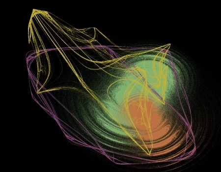
The example above shows the output of a MSG preset that consists of 3 different MSG chaotic attractor processors composited together into a single colorized image. This post will discuss different coloring strategies you can use to build colorized MSG chaotic attractor presets.
BW Attractors
There are a number of different MSG processors that can generate chaotic attractors. These presets typically generate a single channel black and white image. A simple example of a 2 processor MSG preset that generates a black and white attractor image is shown below.
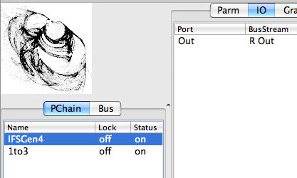
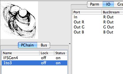
The first IFSGen4 processor is generating the 1 channel black and white chaotic attractor image. Note that it has a single ‘Out’ IO port that is connected to the ‘R Out’ image stream. Since a MSG preset generates a RGB output image, we need to map the chaotic attractor output to all 3 output color channels. A ‘1to3’ processor is used to do this as shown below.
Color Gradient Mapping Color Attractors
A simple approach to building a color image from a 1 channel black and white image is to use color gradient mapping. In this approach the 1 channel black and white image is used as the mapping index into a color gradient. Black (0) maps to the left side of the color gradient. White (255) maps to the right side of the color gradient. Gray values (between 0 and 255) map across the color gradient from left to right. The simple MSG preset below shows a color gradient mapped chaotic attractor.
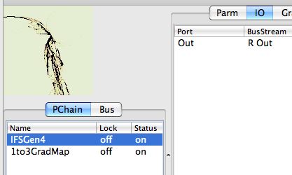
Note that the first step in this preset is the same as the black and white example we started with. The ‘Out’ IO port for the IFSGen4 processor is connected to the ‘R Out’ image stream. The screen shot below shows the IO connections for the second ‘1to3GradMap’ processor.
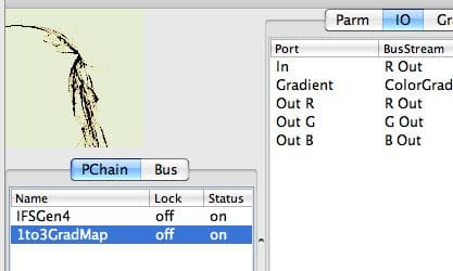
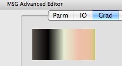
Note that the 1 channel chaotic attractor output is used as the input for the color gradient mapper as specified by hooking the ‘In’ IO port to the ‘R Out’ image stream (remember that the output of the chaotic attractor was placed in the ‘R Out’ image stream in the step above). The ‘ColorGradient’ stream is hooked to the ‘Gradient’ IO port. This color gradient is what is providing the coloring for the colorized attractor output. The R, G, and B output ports are hooked up respectively to the R, G, and B output image streams. The color gradient used in this preset is shown below.
Building up Multiple Color Chaotic Attractors
More complex images can be created by combining together different chaotic attractors that are each rendered in different colors in a single output image. The first image at the top of this post shows off an example of this kind of multiple attractor colorized output. The screen snaps below will show off how to build up this kind of colorized multi-attractor image.
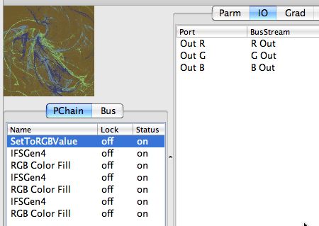
The MSG preset shown above generates 3 different colorized chaotic attractors placed on top of a color background. The first ‘SetToRGBValue’ processor generates the flat color background. You can see that it’s 3 RGB output ports are connected to the main RGB Out image streams.
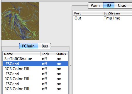
The 3 IFSGen4 processors are generating the 3 chaotic attractors used in the final output image. Remember that this kind of chaotic attractor processor generates a single black and white output channel. Since we are building the final output image in the 3 RGB Out image streams, we set the Out IO port for the IFSGen4 attractor output to connect to a temporary image stream buffer called ‘Tmp Img’. This insures that we can use the attractor output image as an alpha matte in the next step without overwriting and destroying our existing color output in the RGB Out streams.
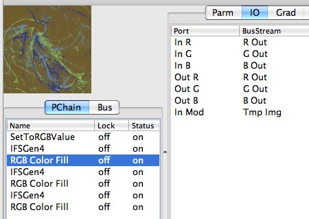
The ‘RGB Color Fill’ processor is then used to composite a colorized version of the attractor output into the RBB Out image streams. If you look at the IO connections above for this processor you can see that the ‘Tmp Img’ stream we placed the attractor output into is used as the ‘In Mod’ port for this processor. This modulation input is used as an alpha channel to composite a solid color into a 3 channel color image. Note that we use the same 3 IO channels for the color input and output, the main RGB Out image streams. This is because we are using these 3 image streams to build up our color output image.
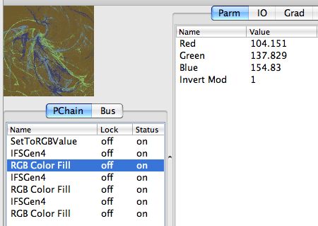
The parameter values for the ‘RGB Color Fill’ processor are shown above. Note that the first 3 parameters specify a specific color. This is the color that will be alpha matted into the 3 channel output image. Setting the ‘invert Mod’ parameter to 1 means that the ‘In Mod’ modulator image stream is inverted and then the inverted image is used as the alpha matte.
The reason why we are inverting the attractor image for alpha matting is that the attractor processor generates a white background with the attractor represented as gray values building up to full black. The ‘RGB Color Fill’ processor composited the full red,green,blue color specified by it’s editable parameters where ever the modulator channel is full on (or 255). Gray values in the modulator channel are alpha matted with the color at reduced luminance values. Black (0) parts of the modulator image will not alpha matte any color into the RGb output. So we want to invert the attractor output when using it as an alpha matte so that the thin attractor lines will fill with color.
The 2 steps of generating a black and white attractor image in the ‘Tmp Img’ image stream and then using that image as an alpha matte to matte in the attractor as solid color are repeated 3 times in the overall preset. This generates a final output image with 3 different attractors matted in with 3 different colors in the final output image. You could use as many different attractors and colors as you wished to build up your final image.
Compositing Color Images with Attractors
Another attractor coloring strategy is to associate each attractor with a specific color image that is then used as the coloring for alpha matting based on the attractor. So instead of matting a solid color like in the example above you use the attractor to matte a color image. The MSG preset below shows off one example of this kind of coloring approach.
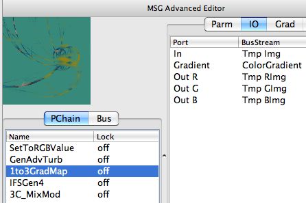
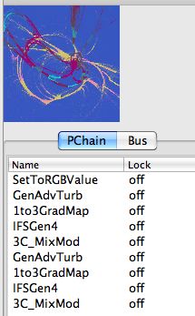
The first step in this preset is the same as before, a SetToRGBValue processor is used to setup a flat color background in the RGB Out image streams. The next 2 processor steps create a random color image in 3 temporary image streams. The GenAdvTurb processor is used to create a random 1 channel black and white texture image in the ‘Tmp Img’ stream. That image stream is then used as input for a 1to3Gradmap processor which uses the black and white texture image as the gradient mapping index to generate a color texture image output in the 3 temporary image streams shown above (Tmp RImg, Tmp GImg, Tmp BImg). This random color texture image will then be used as the color image source for alpha matting with a chaotic attractor.
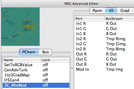
The IFSGen4 processor is then used as in the previous example to generate a 1 channel black and white attractor image in the ‘Tmp Img’ image stream. This black and white attractor image is then used to modulate the 3C_MixMod processor. The 3C_MixMod processor alpha mattes a color image as opposed to the RGB Color Fill processor used in the previous example which matted a solid color.
The IO connections for the 3C_MixMod processor are shown above. Note that the main RGB Out image streams are used to build up the final output image. The Tmp RImg, Tmp GImg, Tmp BImg streams are used as the source of the random color image that is alpha matted by the image specified for the Mod In Port, which is the ‘Tmp Img’ image stream used for the IFSGen4 chaotic attractor output.
Note how the chaotic attractor is colored in with the random color texture field we created. You can build on the approach specified above to use additional attractors that colorize different color texture fields to build up multiple attractor images with more elaborate colorings. The example below shows how to extend the preset to incorporate an additional attractor colorizing a second random color texture field into the final output image.
